PRODUCTS
Yueheng Instrument & Apparatus
PRODUCTS
○ Micro metal tube float flowmeter
○ All stainless steel metal tube float flowmeter
○ Imported series glass rotameter
○ Domestic series glass rotameter

Micro metal tube float flowmeter
MF small golden brick
 |
.jpg) |
.jpg) |
| Side in and side out | Side in and side out | Side in and side out |
.jpg) |
.jpg) |
.jpg) |
| Side in and side out | Lower in and upper out | Lower in and upper out |
MK alarm petty cash transfer
(2).jpg) |
.jpg) |
(1).jpg) |
MK small gold transfer
.jpg) |
.jpg) |
.jpg) |
MT petty cash transfer
.jpg) |
.jpg) |
.jpg) |
| Side in and side out | Side in and side out | Side in and side out |
.jpg) |
||
| Up in and down out |
Flange Xiaojinzhuan
.jpg) |
.jpg) |
.jpg) |
| MF flange connection | MF flange connection | MF flange connection |
.jpg) |
.jpg) |
.jpg) |
| MK flange connection | MK flange connection | MK flange connection |
Anticorrosive
.jpg) |
.jpg) |
.jpg) |
| MF Small gold transfer | MF Small gold transfer | MF Small gold transfer |
.jpg) |
||
| MT Small gold transfer |
Remote transmission small gold transfer
.jpg) |
.jpg) |
.jpg) |
1. Overview
LZZ (D) W series is a micro-flow metal tube float-type flow measuring instrument, which can measure liquid, gas or steam. The instrument adopts the variable area measuring principle, and the measuring part is composed of a conical measuring tube and a float, which has the characteristics of firmness, stability and wide application range. The connection mode includes horizontal connection or vertical connection, and the pressure regulator (constant flow valve) with inlet pressure change or outlet pressure change can also be selected. It is widely used in micro flow measurement and process control in petroleum, chemical, chemical fiber, steel, food, light industry, pharmaceutical and other industries.
LZZW series is a field indicating instrument, which can be equipped with one or two intrinsically safe and explosion-proof alarm switches (associated equipment is required); LZDW series is an electric remote type instrument, which outputs 4~20mA current signal (compatible with HART communication protocol), and uses LED light column to indicate the flow on site.
2. Model designation
|
L Z |
W— |
||||||
|
Z |
Local indication type |
||||||
|
D |
Electric remote transmission type |
||||||
|
Y10 |
Lower in and upper out |
Structural form (medium flow direction) |
|||||
|
Y20 |
Side in and side out |
||||||
|
RR1 |
304 |
Wetted material |
|||||
|
RRL |
316L |
||||||
|
K1 |
With an upper limit alarm point |
||||||
|
K2 |
With a lower limit alarm point |
Additional features |
|||||
|
K12 |
With one upper limit and one lower limit alarm point |
||||||
|
L Z□ W — □ / □ / □ |
|||||||
3. Main technical parameters
1. Measuring range: water (20 ℃) 0.3~100L/h air (20 ℃ 101325Pa) 5~3400L/h
2. Range ratio: 10 ∶ 1
3. Accuracy class: 4.0
4. Working pressure: 2.5MPa or 6.4MPa
5. Medium temperature: - 80~+150 ℃
6. Ambient temperature: - 25~+65 ℃
7. Connection mode: 1/4 ″ NPT internal thread, optional Φ 6( Φ 8) Ferrule connection or according to user requirements 8. Limit alarm: 1~2 alarm switches (optional, explosion-proof grade ExiaIICT3-T6)
9. Electric remote transmission: power supply voltage: 24 (1 ± 10%) V DC
Output signal: (4~20) mA DC, two-wire system (compatible with HART communication protocol) load resistance: ≤ 500 Ω (24V DC)
10. Protection grade: IP67
4. Measuring range
|
Number |
water |
Air |
Pressure loss |
|
(20℃ L/h) |
(20℃ 101325Pa L/h) |
(kPa) |
|
|
Y01 |
— |
5~50 |
1.2 |
|
Y02 |
0.3~3 |
10~100 |
1.4 |
|
Y03 |
0.5~5 |
15~150 |
1.5 |
|
Y04 |
1~10 |
40~400 |
1.8 |
|
Y05 |
2.5~25 |
80~800 |
3.5 |
|
Y06 |
4~40 |
125~1250 |
6.5 |
|
Y07 |
6~60 |
200~2000 |
13.0 |
|
Y08 |
8~80 |
250~2500 |
23.5 |
|
Y09 |
10~100 |
340~3400 |
40.0 |
Note: When measuring liquid, ensure that the working pressure is not less than 2 times the pressure loss; When measuring gas, ensure that the working pressure is not less than 5 times the pressure loss to make the flowmeter work stably.
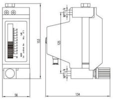
5. Outline and installation dimensions
 |
 |
 |
|
LZZW-()/Y20/RR1 (Horizontal connection) |
LZZW-()/Y10/RR1 (Vertical connection) |
LZDW-()/Y10/RR1/ESK (Horizontal connection) |
6. Main parts
| spare parts | Standards | Special |
| Base | 304 | 316L or according to user requirements |
| Conical tube float | 304 | 316L or according to user requirements |
| Indicator housing | Cast aluminium | |
7. Technical parameters of alarm associated equipment
Micro-flow metal tube float flowmeter with alarm switch shall be equipped with associated equipment. Isolated safety barrier or transistor relay WE77/Ex-1 and WE77/Ex-2 with proximity switch input can be selected.
The transistor relays WE77/Ex-1 and WE77/Ex-2 are composed of power pack, transistor amplifier and intermediate relay. WE77/Ex-1 has one safety control circuit and WE77/Ex-2 has two safety control circuits.
|
Product model |
WE77/Ex—1、WE77/Ex—2 |
WE77/Ex—1D、WE77/Ex—2D |
|
|
Power supply |
220V AC |
24V DC |
|
|
Power consumption |
3.5W |
||
|
Open-circuit voltage |
8V DC(13.5V) |
8V DC(13.5V) |
|
|
short-circuit current |
8mA(31mA) |
16mA(62mA) |
|
|
Allowable inductance |
3mH(31mH) |
1mH(7.6mH) |
|
|
Allowable capacitance |
230nF(609nF) |
160nF(539nF) |
|
|
Input/output circuit |
Single circuit |
Double circuit |
|
|
Switch contact load |
4A/250VA/cosφ=0.7 |
||
.jpg) |
|
| Connection diagram of WE77/Ex-1 and alarm switch | Connection diagram of WE77/Ex-2 and alarm switch |
Including 1: alarm switch 3, WE77 4, power supply 5, output terminal
8. Installation and maintenance
1. Before the flowmeter is installed in the process pipeline, the process pipeline shall be purged or cleaned to prevent impurities in the pipeline from blocking the instrument and affecting its normal use.
2. The flowmeter shall be installed vertically with the medium flow upward, and the included angle between the center line of the flowmeter and the vertical line shall not exceed 5 °.
3. In order to prevent the pipeline from being compressed and deformed, the flowmeter interface must be aligned and parallel to the pipeline axis. If necessary, properly support the pipeline on both sides of the flowmeter to prevent vibration and reduce the axial pressure of the flowmeter.
4. If the medium contains solid impurities, a filter shall be installed upstream of the flowmeter.
5. In order to facilitate maintenance and cleaning, it is recommended to install bypass pipeline.
6. To ensure stable flow indication, it is recommended to install a flow regulating valve downstream of the flowmeter.
7. When measuring liquid, ensure that the working pressure is not less than 2 times the pressure loss; When measuring gas, ensure that the working pressure is not less than 5 times the pressure loss to make the flowmeter work stably.
8. The instrument works based on the principle of magnetic coupling. It should be ensured that the magnetic field generated by other equipment around the instrument will not affect the measurement results.
HOME | ABOUT US | PRODUCTS | HONORS | NEWS | FACTORY | ORDER | JOBS | CONTACT | 中文版
Copyright(C)2022, Changzhou Yueheng Instrument & Apparatus Co., Ltd. All Rights Reserved. Supported by Toocle Copyright Notice 备案序号:苏ICP备09011979号-2