PRODUCTS
Yueheng Instrument & Apparatus
PRODUCTS
○ Micro metal tube float flowmeter
○ All stainless steel metal tube float flowmeter
○ Imported series glass rotameter
○ Domestic series glass rotameter

Turbine flowmeter
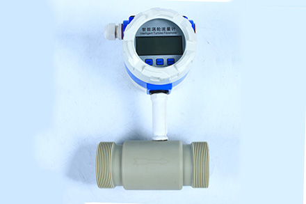
4 6 10 turbine
 |
.jpg) |
 |
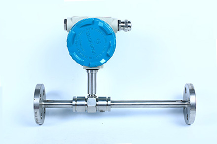 |
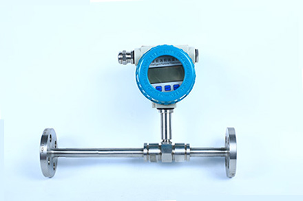
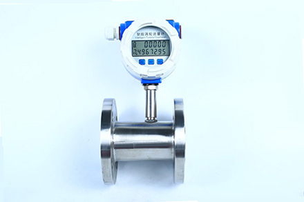
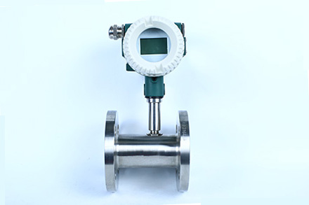
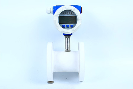
Flange turbine
 |
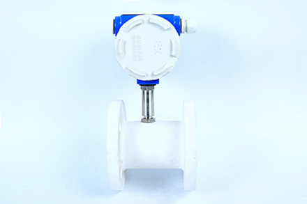
Explosion-proof turbine
 |
.jpg) |
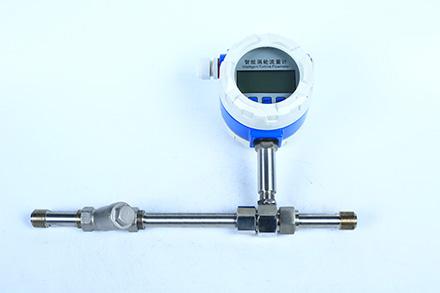
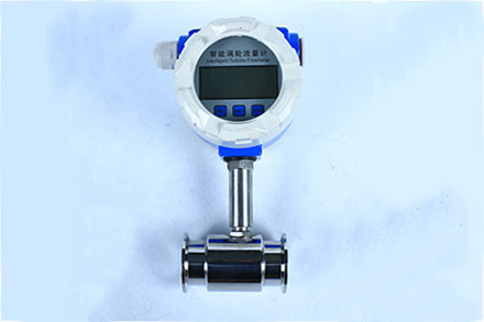
Clamp turbine
.jpg) |
 |
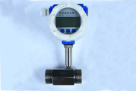
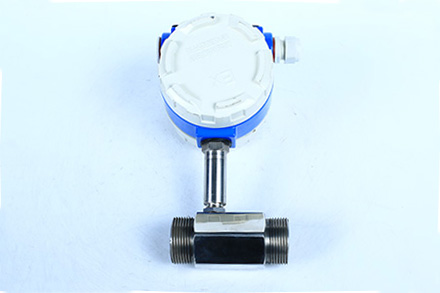
Threaded turbine
 |
 |
All PE turbine
 |
.jpg) |
All-tetrafluoro turbine
 |
 |
Summary
LWGY series turbine flow sensor (hereinafter referred to as sensor) is a speed-type flow instrument based on the principle of torque balance. The sensor has the characteristics of simple structure, light weight, high precision, good reproducibility, sensitive response, convenient installation and maintenance, and is widely used in petroleum, chemical, metallurgy, water supply, paper and other industries, and is an ideal instrument for flow measurement and energy conservation.
The sensor is used together with the display instrument, and is suitable for measuring the liquid in the closed pipeline that is not corrosive with stainless steel 1Cr18Ni9Ti, 2Cr13, corundum AI2O3 and cemented carbide, and free of impurities such as fiber and particles. If it is matched with the display instrument with special functions, it can also carry out quantitative control, excess alarm, etc. The explosion-proof type (ExdIIBT6) of this product is selected, which can be used in the environment with explosion hazard.
The infectious agent is suitable for viscosity less than 5 at working temperature × 10-6 ㎡/s medium, for viscosity greater than 5 × The liquid of 10-6 ㎡/s shall be used after the sensor is calibrated with real liquid. If the user needs to use a special type of sensor, he/she can negotiate to order. If the explosion-proof sensor is required, it shall be explained in the order
Product features
◆ High accuracy, generally up to ± 1%, ± 0.5%, and high accuracy type up to ± 0.2%;
◆ Good repeatability, with short-term repeatability up to 0.05%~0.2%. Because of its good repeatability, such as frequent calibration or online calibration can obtain extremely high accuracy, it is the preferred flowmeter in trade settlement;
◆ Output pulse frequency signal, suitable for total quantity measurement and computer connection, without zero drift, strong anti-interference ability;
◆ High frequency signal (3~4kHz) can be obtained with strong signal resolution;
◆ Wide range, medium and large caliber can reach 1 ∶ 20, and small caliber can reach 1 ∶ 10;
◆ Compact and lightweight structure, convenient installation and maintenance, and large circulation capacity;
◆ It is suitable for high pressure measurement. It is not necessary to open holes on the meter body, so it is easy to make a high pressure instrument;
◆ It can be made into plug-in type, suitable for large diameter measurement, with small pressure loss, low price, and can be taken out without interruption, and convenient installation and maintenance.
Technical indicators
◆ Instrument caliber and connection mode: 4, 6, 10, 15, 20, 25, 32, 40 generally adopt threaded connection (15, 20, 25, 32, 40) 50, 65, 80, 100, 125, 150, 200 adopt flange connection
◆ Accuracy class: 1.0, 0.5, 0.2 (special)
◆ Range ratio: 1:10; 1︰15; 1︰20
◆ Instrument material: 304 stainless steel, 316 (L) stainless steel, etc
◆ Temperature of measured medium (℃): - 20~+120 ℃
◆ Environmental conditions: temperature - 10~+55 ℃, relative temperature 5%~90%, atmospheric pressure 86~106Kpa
◆ Output signal sensor: pulse frequency signal, low level ≤ 0.8V, high level ≥ 8V
Transmitter: two-wire 4~20mADC current signal
◆ Power supply sensor:+12~24VDC (optional)
Transmitter:+24VDC
On-site display type: instrument comes with high-energy king battery
◆ Signal transmission line: shielded cable 3 × 0.3 (three-wire system), 2 × 0.3 (two-wire system)
◆ Transmission distance: ≤ 1000m
◆ Basic type of signal line interface: Hausman connector
Explosion-proof type: internal thread M20 × one point five
◆ Explosion-proof grade basic type: non-explosion-proof products
Explosion-proof type: ExdIIBT6
◆ Protection grade: IP65
| Nominal diameter DN |
L(mm) | G | D(mm) | D(mm) | Number of holes |
| 4 | 295 | G1/2 | |||
| 6 | 330 | G1/2 | |||
| 10 | 450 | G1/2 | |||
| 15 | 75 | G1 | θ65 | θ14 | 4 |
| 20 | 80 | G1 | θ75 | θ14 | 4 |
| 25 | 100 | G5/4 | θ85 | θ14 | 4 |
| 32 | 140 | G2 | θ100 | θ14 | 4 |
| 40 | 140 | G2 | θ110 | θ18 | 4 |
| 50 | 150 | θ125 | θ18 | 4 | |
| 65 | 170 | θ145 | θ18 | 4 | |
| 80 | 200 | θ160 | θ18 | 8 | |
| 100 | 220 | θ180 | θ18 | 8 | |
| 125 | 250 | θ210 | θ25 | 8 | |
| 150 | 300 | θ250 | θ25 | 8 | |
| 200 | 360 | θ295 | θ23 | 12 |
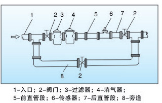 |
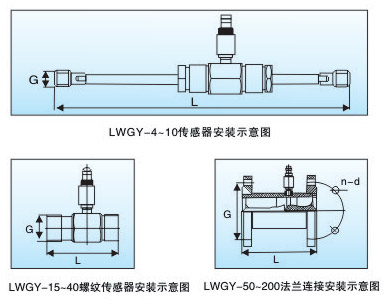
The sensor shall be installed in a place where it is convenient for maintenance and the pipeline is free from vibration, strong electromagnetic interference and thermal radiation. The typical installation pipeline system of turbine flowmeter is shown in the figure. The configuration of each part in the figure depends on the condition of the tested object, and not all of them are required. The turbine flowmeter is sensitive to the distortion of velocity distribution and rotating flow in the pipeline. The sensor should be fully developed to enter the pipe flow. Therefore, the necessary straight pipe section or flow regulator should be equipped according to the type of the upstream choke of the sensor, as shown in the table. If the situation of the upstream side choke is not clear, it is generally recommended that the length of the upstream straight pipe section should not be less than 20D, and the length of the downstream straight pipe section should not be less than 5D. If the installation space cannot meet the above requirements, a flow regulator can be installed between the choke and the sensor. When the sensor is installed outdoors, it shall be protected from direct sunlight and rain.
Installation requirements for connecting pipes
For horizontally installed sensors, the pipeline shall not have visible inclination (generally within 5 °), and the verticality deviation of vertically installed sensor pipeline shall also be less than 5 °, and the fluid direction must be upward during vertical installation. Where continuous operation is required and the flow cannot be stopped, the bypass pipe and reliable stop valve (see figure) shall be installed. During measurement, ensure that the bypass pipe has no leakage. Insert a short pipe to replace the sensor at the position where the sensor is installed in the newly laid pipeline, and then connect the sensor formally after the "line cleaning" is completed and the pipeline is cleaned. Due to the neglect of this work, it is not uncommon for the sensor to be damaged by wire sweeping. If the fluid contains impurities, a filter should be installed on the upstream side of the sensor. If the flow cannot be stopped, two sets of filters should be installed in parallel to remove impurities in turn, or an automatic cleaning filter should be selected. If the measured liquid contains gas, a degasser shall be installed on the upstream side of the sensor. The drain outlet and degassing outlet of the filter and degasser shall lead to a safe place. If the installation position of the sensor is at the low point of the pipeline, in order to prevent the impurities in the fluid from deep retention, a drain valve should be installed in the following pipeline to discharge the precipitated impurities regularly. The flow regulating valve shall be installed at the downstream of the sensor. The stop valve at the upstream side shall be fully open when measuring, and these valves shall not produce vibration and outward leakage. Check valves shall be added for the process that may produce reverse flow to prevent reverse flow of fluid. The sensor shall be concentric with the pipeline, and the sealing gasket shall not protrude into the pipeline. The liquid sensor should not be installed at the higher point of the horizontal pipeline, so as to prevent the gas focused in the pipeline (such as air mixed in the flow stop) from staying at the sensor, which is difficult to discharge and affects the measurement. The front and rear pipes of the sensor shall be firmly supported without vibration. Thermal insulation measures shall be taken for the sensor and its front and rear pipes for the fluid that is easy to condense.
measuring range
| Instrument caliber (mm) |
Normal flow range (㎥/h) |
Extended flow range (㎥/h) |
Normal withstand pressure (MPa) |
Pressure withstand grade (MPa) (Flange connection mode) |
pressure loss (MPa) |
| DN4 | 0.04~0.4 | 6.3 | 12、16、25 | 0.12 | |
| DN6 | 0.06~0.6 | 6.3 | 12、16、25 | 0.08 | |
| DN10 | 0.15~1.5 | 6.3 | 12、16、25 | 0.05 | |
| DN15 | 0.4~8 | 6.3、2.5(flange) | 4.0、6.3、12、16、25 | 0.035 | |
| DN20 | 0.45~9 | 6.3、2.5(flange) | 4.0、6.3、12、16、25 | ||
| DN25 | 0.5~10 | 6.3、2.5(flange) | 4.0、6.3、12、16、25 | ||
| DN32 | 0.8~15 | 6.3、2.5(flange) | 4.0、6.3、12、16、25 | 0.025 | |
| DN40 | 1~20 | 6.3、2.5(flange) | 4.0、6.3、12、16、25 | ||
| DN50 | 2~40 | 2.5 | 4.0、6.3、12、16、25 | ||
| DN65 | 4~70 | 2.5 | 4.0、6.3、12、16、25 | ||
| DN80 | 5~100 | 2.5 | 4.0、6.3、12、16、25 | ||
| DN100 | 10~200 | 1.6 | 4.0、6.3、12、16、25 | ||
| DN125 | 13~250 | 1.6 | 2.5、4.0、6.3、12、16 | ||
| DN125 | 15~300 | 1.6 | 2.5、4.0、6.3、12、16 | ||
| DN200 | 40~800 | 1.6 | 2.5、4.0、6.3、12、16 |
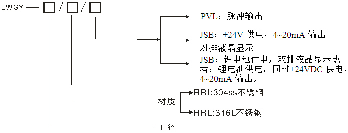
Model selection
HOME | ABOUT US | PRODUCTS | HONORS | NEWS | FACTORY | ORDER | JOBS | CONTACT | 中文版
Copyright(C)2022, Changzhou Yueheng Instrument & Apparatus Co., Ltd. All Rights Reserved. Supported by Toocle Copyright Notice 备案序号:苏ICP备09011979号-2